
The connection for the segment mode is easy. Simply connecting channel 1 of the analyzer to one segment, channel 2 to the other segment. Do not forget to connect the ground line, which is a common recommendation for a correct working bus to avoid equalizing currents through the bus lines. Both segments do have the same electrical potential, the isolation only refers to the data stream.
One important hint: The segmentation works only if the analyzer is powered and loaded, the analyzer program must run. If the analyzer does not work the route through the analyzer is broken, the complete bus communication will be interrupted.
As mentioned in the part “How does the segment mode work” the correct function depends on the ability to detect the active and inactive bus states. This can be ensured only if the termination of the segments are correctly established.
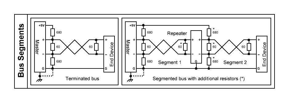
Assumed that the original bus was correctly terminated with 2x120Ω at the ends and pull up/down resistors (mostly 2x680Ω) to set the inactive state to 200mV difference (as required for RS485) then these resistors have to be doubled to meet these requirements on both segments. See also the connection scheme in the analyzer program wiring setup.
A bus with two devices without and with repeater (analyzer segment mode) and the correct terminations:
All entries concerning the segment mode: