

Introduction
The segment mode is a very powerful extension to the RS485 analyzer to find faulty activities or data on a bus, even if a lot of (or only two) bus devices share the same line so that the faulty activity can not be directly assigned to a certain sender.
Usually there is a rough or specific idea about which device does not work correctly. If this device or group of devices can be isolated (not electrically) from the rest of the bus the data on the bus can be directly assigned to this isolated group or device and the rest of the bus.
This is what the segment mode of the analyzer provides. The bus is split into two segments of any size and the common data on the bus can be unequivocally assigned to a sender in the correct segment. By variations of the two segments the faulty device can be encircled and detected.
How does it work?
In general the segment mode works like a good repeater. The bus is cut into two segments with any number of devices on both sides. Both segments have bidirectional RS485 transceivers for receiving or sending on the bus. In the following we also use the name repeater for the segment mode extension of the analyzer.
Between these segment transceivers a bidirectional switch with special controller cares for the data exchange in either direction or disabling on both sides.
At first both segments are inactive, no device sends and also the transceivers of the analyzer are inactive. The bus is undriven and floating, the levels set by the termination and pull resistors.
The analyzer or repeater detects activity on one of the segments due to a sending device. It sets the switch so that the data is sent from the active side to the inactive one. In doing so the inactive side is now active as well.
After detecting the direction the incoming and logged data can be assigned to the correct segment which was the goal.
As now both sides are active the switch must not be changed until the sending device stops sending and releases the bus. When new inactivity is detected the second segment is also released, both segments become inactive again.
How bus activity is detected
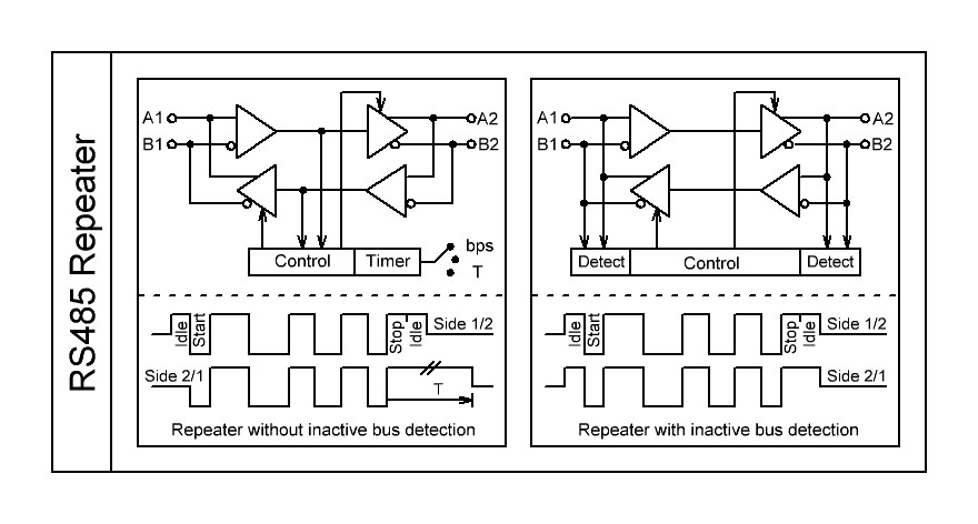
The main challenge for the switch controller is to detect the active and inactive bus states correctly. A standard RS485 repeater detects activity with the first signal edge of an asynchronous data packet, the edge of the start bit. The disadvantage is that the usual active idle state one bit before the first data edge is not detected and passed. The end of transmission is set when no signal edges are detected within one character length, depending on the bit rate, mostly set by inaccurate RC delays, a further disadvantage.
The switch controller of the Analyzer does not only detect and evaluate the edges but also analyzes the bus difference voltage to decide if the bus is active or not.
If the bus is undriven, the difference voltage between D+ and D- is 0V, through the 120Ω termination resistors, to 200mV, set through the pull up and down resistors. The analyzer detects this condition with an extended voltage range of about 0 to 600mV to cover voltage variations by inaccurate terminations.
In this way the precise detection of inactive and active state is possible and used for controlling the direction and enabling of the data switch. The early bus enabling before the first edge is ensured as well as the fast bus disabling after the last sent bit plus one idle bit time.
The bus behavior of the sending device in one segment is exactly copied to the other segment.
A comparison of the two switching variants of a repeater:
How do I connect the analyzer?
The connection for the segment mode is easy. Simply connecting channel 1 of the analyzer to one segment, channel 2 to the other segment. Do not forget to connect the ground line, which is a common recommendation for a correct working bus to avoid equalizing currents through the bus lines. Both segments do have the same electrical potential, the isolation only refers to the data stream.
One important hint: The segmentation works only if the analyzer is powered and loaded, the analyzer program must run. If the analyzer does not work the route through the analyzer is broken, the complete bus communication will be interrupted.
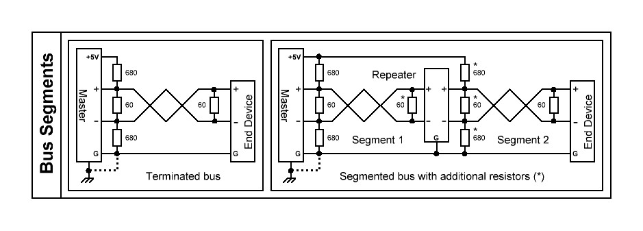
As mentioned in the part “How does the segment mode work” the correct function depends on the ability to detect the active and inactive bus states. This can be ensured only if the termination of the segments are correctly established.
Assumed that the original bus was correctly terminated with 2x120Ω at the ends and pull up/down resistors (mostly 2x680Ω) to set the inactive state to 200mV difference (as required for RS485) then these resistors have to be doubled to meet these requirements on both segments. See also the connection scheme in the analyzer program wiring setup.
A bus with two devices without and with repeater (analyzer segment mode) and the correct terminations:
What if it doesn't work?
The analyzer is connected in the segment mode (bus routed through the analyzer) and the communication is interrupted or data can be sent only in one direction. The communication without analyzer works.
Reasons
There can be two reasons for this behavior.
1) One or both bus segment(s) is not correctly terminated and biased as recommended for RS485 buses. In the inactive bus state the difference voltage is higher than about 600mV. In this case the analyzer interprets the bus segment as active and sets the direction of the routing switch from the active segment to the other. As no inactivity is ever detected the switch will never change and the bus is never released.
2) Just the opposite behavior. The bus is overloaded or one device defective so that the bus swing is not more than ±500mV. In this case the analyzer will never or seldom detect an active bus, the routing switch is closed and the transceivers disabled.
Check
Remove the analyzer and recombine the segments. Connect the analyzer in tap mode with channel 1 parallel to the bus. Now start the communication and do a short logging. Open the signal view and check the data signal. Now examine the signal before and after a transmission byte sequence. In case 1 you will note that the bus is not released down to a difference voltage of <600mV, the signal line will be high between the packets of different sender instead of being displayed in the middle between high and low, which is the inactive state. In case 2 the signal is always or most time in the middle, even if bytes are transmitted.
Remedy
At first check if the resistors are correct as described above. Use a multimeter to measure the voltage difference A+ - B- in the inactive state (transmission not started). It must be between 200mV and 300mV as a recommendation. Furthermore use a digital scope to verify that the bus and its voltages (swing at least 1V) are correct over the complete time. Use repeaters if the bus is overloaded.
The error behavior of the segment mode can be a hint for a bus working at its limits. You should follow this hint and optimize the bus, otherwise sporadic faults can happen. That is what the analyzer is made for, giving indications of error sources.