
The knowledge of the low level asynchronous protocol is absolutely required for all persons who have to examine the serial data stream on bit basis. Errors can be found and removed only with the basic understanding of the asynchronous data transmission.
The following PDF shows this kind of transmission and its bits and error flags in detail.
These are the chapters and topics:
-
Signal level and synchronization shows condensed how the bits are physically on the line
-
The asynchronous data chapter contains information about the bits. Start bit, Data bits, Parity bit and Stop bit are described.
-
Especially the extra (parity) flag is described since it has a lot of new versatile applications in addition to the parity function. The bit is used not only for odd parity, even parity or none parity, but also as address bit, 9th data bit (9 Bit protocol) or as mark, space placeholder.
- The transmission error chapter reveals the secrets about the parity error, framing error and break.
General
The “asynchronous” data transmission is a way to send and receive data over a serial bus when no data cock is available in parallel. The data is sent over the lines in a bit rate clock which shall be the same in the sender and receiver.
The asynchronous data are simply bits on the line which have to be assigned to the real data payload. Characters and bits are sent one by one, the number of payload data bits are fixed. The assignment is done in the UART (Universal asynchronous Receiver Transmitter).
The following chapter describes the well defined protocol.
Physical appearance
Signal level
The standard line code for the transmission is NRZ-L (No Return to Zero, Level). This means that both logic values are simply represented by two different bus signal voltages which are depending on the used transmission standard, RS232, RS422/485 or others.
The logical values are inverted to the physical voltages. A logical ’0’ after the UART is output as a positive voltage or voltage difference, a logical ’1’ as 0V or a negative voltage difference. The reason is that logical ’0’ (idle bus condition) can be distinguished from the power down condition. To achieve this the level converters (e.g. digital to RS232) invert the level. As a compensation the UARTs invert the logical bit stream again.
Synchronizing
Due to small differences in the bit rate clock in both (or more) devices the receiver has to be re-synchronized with the sender after some bits to make sure that following bits will be sampled in about the middle of the bit.
As no timing reference is available within the bit stream the data have to be supplemented with definitive information about the beginning and the end of each byte. This information -additional start and end bits enclose the data payload- can be used to synchronize the data sampling unit to regain the original parallel data.
The start bit drives the bus from idle to active. This negative going edge is used to synchronize the data sampling unit. The stop bit is used to get a save return to the idle state with at least one bit gap to the next possible start bit.
In this way both bits are the source for a successful synchronization of the data recovering unit, but with the disadvantage of additional bit overhead. This reduces the data throughput to 80% for 8 bit data. Also the bit rates of the sender and receiver must be very close to each other, the difference should be not more than 1% for each device, 2% together.
Asynchronous data
The data scheme is always the same, the total bit length per character depends on the quantity of data, parity and stop bits, called frame. The bit sequence and number is:
| Start | Data | Parity | Stop |
|---|---|---|---|
| 1 | 5 to 8 | 1 or none | 1 or 2 |
Of course the number of bits, which are used in a specific transmission, must be known to all attached bus devices. It is the so called low level transmission -frame- protocol and is described by a sequence of characters, representing the number of data bits, the used parity and the number of stop bits. One start bit is always necessary and assumed.
The abbreviation 8N1 means: 8 data bits, No parity, 1 Stop bit. This is the most used protocol.
Minimum number (5N1) is: 1+5+0+1 = 7 bits.
Maximum number (8X2) is: 1+8+1+2 = 12 bits.
More than 12 Bits altogether per frame are not allowed, the limits for the bit rate variation would be to narrow. This is reserved for synchronous transmission with increased re-synchronization capability.

These are the bits in detail:
Start bit
The start bit is the necessary transition from idle ’0’ to active ’1’ which synchronizes the bit counter in the receiver, it can not be left. So the stop bit is logical ’1’. There is nothing more to say about it.
Data bits
Standard UARTs are connected to the microprocessor via byte interfaces, so sending of more than 8 bits at a time is not possible in a single access. That limits the single data to 256 states, but of course bytes can be linked to words and fields in a multiple of 8 bit. Sending 8 bits seems to be natural for a byte connection, but why using less than 8 bits in the data stream?
There is an easy explanation. With every bit, which is not transferred, the throughput is increased by 10% compared to a 8N1 transmission. Especially for older transmission devices like Telex with traditionally low transmission rates this can be of big advantage. You can transfer the ASCII character set with 7 bits (128 states) or reorganized with only 6 bits (64 states). A machine might be controlled with 32 commands (5 bits). Less than 5 bits does not make much sense.
This fact of possible different data sizes is the reason for another peculiarity of the data bit assignment: The data is sent low significant bit (LSB, Data bit D0) first over the line. The trick is that if a communication at first needs only few bits (or states) data can be sent with reduced length. But if you once need to transfer more information in more bits you can increase the bit length without having to reassign the bits. Bit D0 is always at the low end of the data Byte which is transferred from or to the microprocessor. Bits which are not used are always ’0’.
Extra (Parity) bit
The parity bit was once added to check if the data was correctly received. Meanwhile this extra bit has a more versatile status. The following usages are known, each with an identification letter:
N: None, As the name says... The bit is omitted
P: Parity, This is simply a placeholder for a parity bit which is either unknown yet or can be set dynamically.
E: Even (Parity), The parity bit is evaluated in the following way: All data bits which are ‘1’ plus the parity bit of the frame are counted, the sum must be a multiple of 2. Examples:
Data = 11010010 => 41 => parity bit = 0 (41)
Data = 11011010 => 51 => parity bit = 1 (61)
O: Odd (Parity), The inverted parity to Even, the sum of all ones must be a multiple of 2 + 1. Examples:
Data = 11010010 => 41 => parity bit = 1 (51)
Data = 11011010 => 51 => parity bit = 0 (51)
A: Address, This bit has the function to differ between bus address of a device (‘1’, first byte(s)) and data information (‘0’, following bytes). In this way device addressing in the first byte is much faster than spending an extra data frame for this purpose. The eight data bits plus address bit is also known as “9 bit protocol”
D: Data, The bit is used as a ninth data bit, which is a rare use since the setting of this bit for every byte takes a lot of time and speed.
M: Mark, The parity bit is set to a fixed ’1’. It is also used to set the bit when used in the A or D mode.
S: Space, The parity bit is set to a fixed ’0’. It is also used to reset the bit when used in the A or D mode.
X: undefined, Used for general descriptions. The bit is available for whichever purpose.
The necessary subset is N,E,O,M,S which can be set in a standard UART. The parity setting (E,O) and detecting is directly done by the UART hardware.
Setting and recovering the value for A or D takes a lot of computing power because this is possible only with the indirect way of setting M, S and evaluate the parity error flag as described in chapter „parity“.
Stop bit(s)
Like the start bit is necessary to indicate the start of a frame with the transition from idle to active the stop bit finishes the frame with a safe return to idle. So the stop bit is logical ’0’.
Only one stop bit is necessary for correct decoding, the following bit can be the start bit of the next frame. To give the receiving decoder more time to transfer the detected byte to its internal output buffer a further stop bit can be added before the next start bit.
Generally every further stop bit extends the gap to the start of the next frame, so these additional stop bits are simply idle conditions.
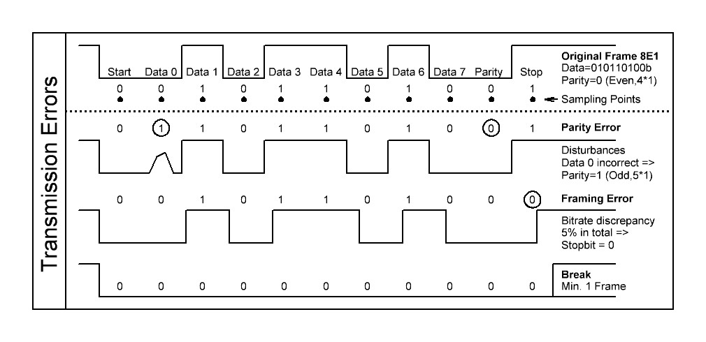
Transmission errors
The receiving UART can detect three types of extraordinary conditions which have to be treated as errors or additional information. They are described in their priority. Only the flag with the highest priority has to be regarded if more than one erroneous condition occurs.
Before searching for ominous errors make really sure that all attached bus devices have the same low level protocol settings, unintended different settings are the main reasons for an inexplicable error behavior.
Parity low priority
If the parity bit is really used as a parity and if the evaluated parity of the received data does not fit to the received parity than a parity error is indicated. The reason is that the single data bits were not correctly caught, mostly because of disturbances on the line.
With one parity error you can detect that an odd number of received bit including the parity itself is wrong, but you can not assign and correct the bit(s).
The standard handling is to send an request for repeating the whole transmission, depending on the used high level protocol. It is important for a reliable transmission not to ignore this error like many program(er)s do because they do not know how to handle this condition.
If the parity bit is used as an universal address or data bit (A or D) the handling of this condition is different. In this case it is not used as an error flag. The value of this bit must be computed since the standard UART does not directly offer the output of the parity bit.
That needs a bit more software handling. The way to gain the A or D bit is:
Set the parity to Odd or Even generally.
Get the data byte plus the parity error flag.
Evaluate the correct parity from the data.
If no parity error is flagged: The evaluated parity is the transmitted bit.
If a parity error is flagged: The evaluated parity is the inverted bit.
Example:
Set the parity to even (8E1), Get the data: 23h = 00100011b, Evaluate the even Parity: => P=1 (4*1)
No Parity Error: The received bit is ‘1’, Parity Error: The received bit is ‘0’
Framing middle priority
The framing error is a more serious problem and has influence on the whole transmission. It occurs if the receiver awaits a ’0’ stop bit but instead samples a logical ’1’.
If the frame does not return to idle the next start bit can not be detected and so the receiver will get out of synchronization for the following frames. The whole transmission must be thrown away.
How can this happen if the frames are well defined? Three reasons are possible.
First, like for the parity error, a disturbance on the line can lead to an incorrectly sampled logical value. Second, like mentioned before, the settings can be different.
But the most difficult to find error is a variance in the baud rate of sender and receiver. An error of 5% adds up to 1/2 bit for the 10th bit.
This needs a lot of investigation and good examination tools.
Break high priority
A break is present if the line stays in the active state (logical ’1’, physical ’0’) for more than one data frame, no stop bit comes.
This state can be reached intendedly or unintendedly. The latter case is caused by a powered off sender, the interface lines are drawn to ground, the complete communication is halted and broken down. You can’t have a more serious problem.
But the break can also be a triggered by software, it is a settable state in the UART. The meaning is to generate a special condition for all receivers to execute predefined sequences, independent of any transmission. Therefore a longer minimum time for the break can be specified to make sure the condition is correctly detected. Also short and long breaks with different meanings can be used.
The behavior on detecting the break condition depends on the application. Three types are mainly used, some more can be implemented:
-
Resetting the complete device. This affects not only the interface part but also all internal and externally attached hardware like sensors and actuators. It is like a complete system restart after power up. If the master is powered down or up all devices will follow, simply by detecting the break condition.
-
Resetting the interface. This can be used to shut down permanent talkers. Also generally useful for restarting in known conditions, e.g. the interface can be switched to an alternative bit rate by software.
- Subdivide data strings. Some high level data protocols use this special condition to start or end a sequence of transmitted data.
Asynchronous Data Transmission as PDF