
The MSB-RS232/485 analyzers are used to find errors in the high level protocol of the data stream or in the low level protocol of the field bus transmission. A unique feature to find transmission errors is the signal view window where the incoming signal is represented as the decoded logical value ’0’ or ’1’.
The following document shall help you to find out transmission errors with the help of the signal view. Its display of the logical values has some advantages over the display of the analogous signal of a digital scope. While the analyzer decodes what the bus devices decode, the scope only sees the data lines. It is sometimes hard to decide from the scope function which logical data is just being decoded, especially at the signal edges.
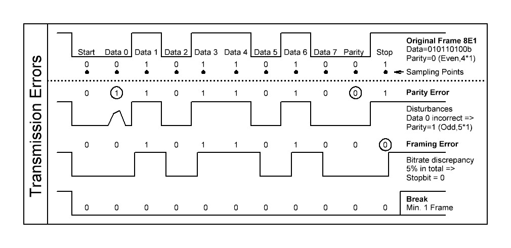
Standard transmission errors
The following error conditions are common for the asynchronous transmission of RS232 and RS485. It is the Parity, Framing and Break error. These errors are flagged with a small ‘P’ , ’F’ , ’B’ in the signal and data views.
The occurrence of these errors are always a hint that something is wrong, either in the interface settings, the bit rate precision or disturbances on the bus.
To understand the cause and removals of these conditions here some short background information.
Structure of the data frames
In asynchronous transmission the data lines are sampled from the first negative edge of the start bit (synchronization edge) over the data bits and the parity until the last bit, the stop bit which has to be ’1’. In older slow devices two stop bits are required to have more processing time. These bits together are called frame.
Sampling takes place in steps of 1/Bitrate. The length (total number of bits) is set by the transmission settings of data and parity bits (called protocol settings).
The number of data bits can be 5 to 8 bits and the bits start with the lowest one D0.
The parity can be none (omitted) or even or odd. The parity bit can also be used for special purposes like address bit (9 Bit protocol) and is always the last bit before the stop bit.
The parity value is depending on the total number of logical ’1’ bits in the frame. The parity bit completes the number to either an even or odd value. If there are five ’1’ bits in D0-D7 an even parity is ’1’, an odd parity ’0’.
The official naming is DPS with D: number of data bits (5-8), P: Parity (Even, Odd, None), S: Number of stop bits (1,2).
Most used: 8N1 with a total frame length of 10 (1 start bit, 8 data bits, 0 parity, 1 stop bit).
Error description
Break, ‘B’:
If all the the frame bits are low for more than the total frame length (no stop bit) than we talk about a break condition.
A break does not have to be an error, mostly it is an intended line condition and can be triggered by the master device. It can be used for:
- Resetting the complete device. It acts like a hardware reset and also occurs on master power up or down.
- Resetting only the interface of the devices. Used to restart the interface management if devices are out-of-control, e.g. permanent talkers.
- Some high level protocols use the break to subdivide the data streams (start or end sequence)
So the ‘B’ flag is more an information than an error flag. Normally nothing has to be done to remove this occurrence. If a break is indicated always a framing error occurs and a parity error might occur.
Framing, ‘F’:
A framing error occurs if the sampled stop bit (last bit of a frame) is not ’1’. The reasons can be:
- Disturbances on the stop bit with wrong sampling
- The total number of frame bits is incorrect, the sender and receiver (analyzer) have different frame (protocol) settings. e.g. 7N1 instead of 8N1.
- The bit rate is not correct. Either the setting or the precision of the bit generation.
- Disturbances on the line or wrong bus termination (biasing).
- A break was just received.
Framing errors normally do not occur in every frame, even if the all the frames are wrong. The error is only indicated if the sampled stop bit is accidentally ’0’, which depends on the bit that is sampled instead.
Parity, ‘P’:
A parity error occurs if:
- the sum of the received data bits does not meet the received or set parity. Receive errors occur due to noise or other disturbances on the line.
- the received parity itself is wrongly sampled due to disturbances.
- the sender or analyzer uses a wrong parity setting.
- the transmitted parity bit is no parity, but a data bit. It also can be an address bit.
- the frame data bit setting is wrong, the total bit length is incorrect, the last data bit or the stop bit could be interpreted as the parity bit. In this case also framing errors will occur since the stop bit might be ’0’ instead of ’1’.
- the bit rate is not correct. Either the setting or the precision of the bit generation.
A break was just received.
Parity errors can occur in every frame or only in some frames, depending on the cause for the error.
If a parity occurs in every frame than the parity is set inverted, odd instead of even and vice versa.
If the parity occurs in some, but not in all frames, then this bit might be used not as a parity but a any data bit. One common error is to set the analyzer and/or device to 7E1 or 7O1 instead of the used 8N1. That means that there is no parity at all in the transmission but a protocol with parity was assumed.
Error investigation
The most important hint to remove these errors is, even if it is obvious:
Before searching for ominous errors make sure that all attached bus devices really have the same low level protocol settings, unintended different settings are the main reasons for an inexplicable error behavior.
To check the correct protocol settings the analyzer has two convincing features, the protocol scanner and the bit ruler.
The protocol scanner
The first step to check the protocol settings is to start the protocol scanner from the main bar with “settings->Scan Protocol“ (or simply the „open scanner“ button) and „Start“. A running transmission with a sufficient number of data frames is required.
The scanner will display the measured bit rate and the detected protocol if possible.
After detecting the protocol you can force the analyzer to use it with „use scan“.
In case no detection is possible at all take a look at this extra document:
MSB Protocol Scanner
The bit ruler
The next step in examining the errors is to use the signal window together with the bit ruler.
The bit frame ruler can be activated at the bottom of the signal view for one out of the 8 modem lines (usually RXD or TXD). With the set button you can vary the default settings (which the analyzer uses to log the data).
The ruler is attached to cursor 1 and can be shifted along the signal view to examine single frames.
Example for a correct data frame 8N1:
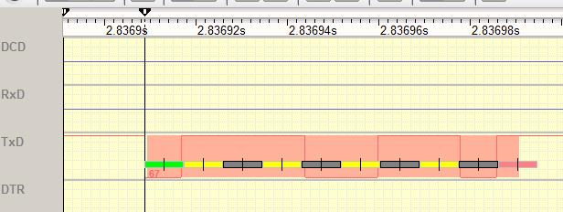
The ruler shows the bits in different colors: Green is the start bit, yellow the even data bits, gray the odd data bits. If a parity is enabled it is shown in blue and red marks the end of the frame, the stop bit.
The middle of each bit (small line) is the sample point for the bit decoder.
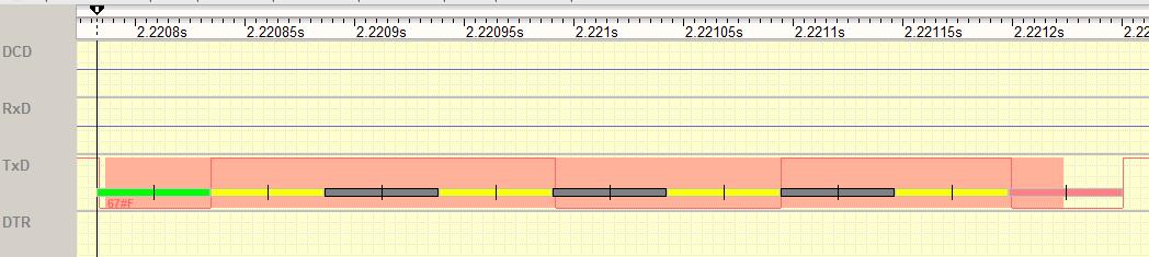 The above example shows a framing error (displayed below the green start bit as 67#F). A data frame of 67 hex was received with framing error. As you can see the stop bit is ’0’ instead of ’1’. The reason is that the analyzer was set to 7N1 instead of 8N1, the last data bit D7 is seen as the stop bit.
The following picture shows an incorrect set bit rate. Instead of 19200 the double rate was set at the analyzer. The sample points seems to fit but the ruler spans over two frames.
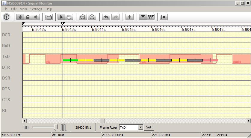
The ruler itself can be set to different parameter combinations to fit to the received frames. In this way the correct setting can be found out if and compared to the analyzer settings and scan results. For the ruler setting click on „set“ at the bottom of the signal view at the right of the ruler signal select.
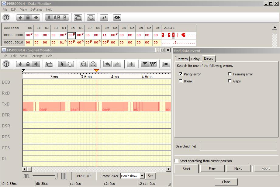
Error navigation
With the help of the view synchronizing feature of the analyzer you can easily jump from one error to the next to check the according logical signal:
Open the data monitor which shows the received data with the „P“,“B“,“F“. Open the Find Dialog from the menu. Tick the errors you search for. Set the signal view to be synchronized from other views (the arrow to the left).
Every click on „Next“ in the search dialog will Jump to the next occurring error in the data view and also in the signal window.
Conclusion
The MSB Analyzer is an ideal tool to search for transmission errors caused by differing transmission protocol settings or by external influences like noise and bursts on the lines.
All views of the analyzer interact synchronized to get the best result to find out the reason for transmission errors.
Nevertheless the analyzer can only help to get a clue of the cause for the error, the decision if the settings are incorrect at any bus participant or if there are other influences has to be made by the user.
This article as PDF