The following document describes the way how the logic mode can be used. At first we examine the way a single bit takes through the bus and processing unit. So we get a bit background information.
Then we assume that a serial digital signal from any system shall be directly connected without RS232 conversion to the analyzer for logging purposes.
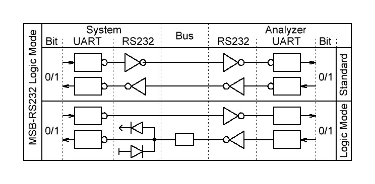
Standard RS232 transmission
The RS232 transmission uses inverting RS232 senders and receivers to convert between digital and RS232 signals. To compensate these invertings additional inverters are integrated in the digital logic which does the parallel to serial conversion and back, the UART (Universal Asynchronous Receiver and Transmitter).
So the sent original parallel data bits at the sender side are four times inverted on their way to be processed as parallel data at the receiver side.
Logic mode transmission
The MSB-RS232 logic mode allows to directly connect a logic serial data signal from system UARTs to the analyzer without the need of adding a RS232 chip to meet the levels of the analyzer ports.
For this reason the logic mode simply omits the internal inverting at the UART. In this way the inverting of the analyzer’s RS232 transmitter chip is compensated.
The electrical parameters of the analyzer ports are not changed, so the inputs and outputs are still RS232 level connections.
Using the inputs of the analyzer
For the inputs you have to regard the following:
- The trip point of the receiver to switch between the logic values is about 1.5V which should work for every system voltage between 2.5 to 12V. A negative voltage does not have to be applied.
- The input resistance of the RS232 receiver is about 5kOhm which might be too low for low energy systems. With a +5V signal you get 1mA active current.
- Connect the data output lines to the following analyzer input port pins:
RXD to pin 2 of port B, TXD to pin 3 of port A, Ground to pin 5 of either A or B.
Using the outputs of the analyzer
If you want to use the outputs of the analyzer, e.g. in connection with the RS232 switch option you have to act cautiously:
- The problem is that the output swing is between -5V and +5V. At least the negative voltage is dangerous for your digital logic. The way to cut the voltages is the following:
- Use a series resistor of 1kOhm to 10 kOhm, depending on the used bit rate and input resistor of the system logic. That should already work because most logic inputs have the necessary clamping diodes integrated.
- If you want to be sure that the RS232 level does not do any harm you can use additional shottky diodes to ground and system voltage.
- Connect the data input lines to the following analyzer output pins:
RXD to pin 3 of port B, TXD to pin 2 of port A. Ground to pin 5 of either A or B.
Analyzer connection pins at port A,B for further digital signals can be found in the installation chapter of the manual.