
One of the oldest standards is EIA232, often declared as dead, but still alive with steady application fields, thanks to its very easy way of usage, combined with a good noise immunity. It is used for point-to-point (PTP) asynchronous transmission, typically as a controller interface when high data rates are not needed, but the focus is on save communication.
Electrical side
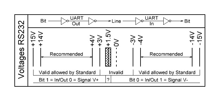
RS232 is a bipolar inverting interface. Logical Zero is represented by a positive voltage of +3V to +15V, logical one by a negative value of -3V downto -15V. There is a gap between -3V and +3V where the logical value is officially not defined. The trip point is about +1.5V
PCs with a RS232 connector mostly have ±12V, standard Interface chips use ±5V.
Please note that there is a double inversion between the logic bit value and the RS232 signal. The first inversion is done in the data processing UART, the second inversion in the RS232 driver. So a bit value of 0 is output at the Uart as logical 1 and then inverted to a negative voltage on the RS232 line.
The input resistance of the standard receivers is about 5kΩ. For the output applies: resistance 300Ω, standard load maximum capacity 2500pF, with a maximum short circuit current of ±10mA for charge pump based interface chips.
When using a Led tester or analyzer the negative voltage -Idle state- (logical 1) is displayed green, the positive voltage -active state- (logical 0) is displayed red.
The following diagram shows the voltage ranges. Turn it 90° clockwise.
Transmission rate and cabling
The RS232 interface was designed for low transmission rates. Transceivers for up to 1 Mbps are now available, rare types offer up to 1.5 Mbps. PC-standard today is 230400bps (if installed at all), higher rates can be processed with USB to RS232 converters.
The RS232 cable length has to be adapted to the used bit rate. A measurement shows that a shielded RS232 cable has a capacity of 50 to 100 pF/m. Together with the output impedance of the drivers (300Ω) we get a nice low pass signal filter (t=RxC) which leads to round edges in the bit stream. The higher the bit rate the shorter the cables have to be! That seams to be clear but often gets forgotten. And some applications switch their transmission rate while working, e.g. from 9600bps after reset to 115200bps for faster data transfer.
We recommend to restrict the cable length according to the bit rate using the formula L=500kbps*m/BR. This means 50cm cable for 1Mbps, 4m cable for 115200bps or 50m for 9600bps. Line drivers work faster with ±5V than with ±12V because of the smaller voltage swing.
The standard RS232 cable is shielded and has a 9 pin D-sub male and a 9 pin D-sub female connector at its ends. All pins are directly connected with 9 wires, Pin 1 to 1 until 9 to 9. These cabling is called 1:1, there is no crossing and a definite gender changing.
Handshake lines
The first devices which were operated with RS232 levels were data modems -devices to transmit data over telephone lines- used by Telex, Fax and others. To remotely control these modems a set of 8 handshake lines were defined. Even if these modems are no longer in use the lines are still available in standard RS232 connectors.
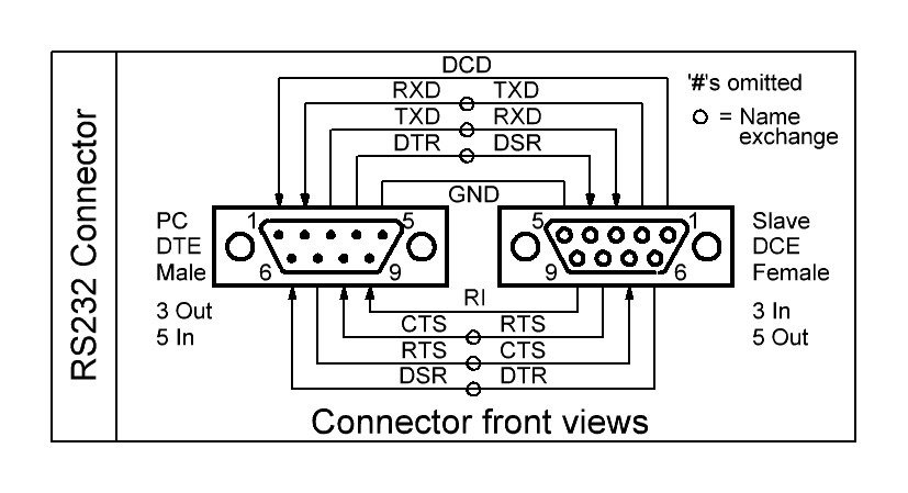
TXD, RXD (or TD,RD) are the data lines. RTS, CTS, DTR, DSR are used for Transmission control, see next chapters.
Two are still to be mentioned. DCD and RI.
DCD means Data Carrier Detect and signals a valid transmission signal to the controlling master device, independent of the transmitted data. It is just the same as if you pick up the telephone receiver and hear the free line signal, a transmission can begin.
RI is Ring Indicator and this exactly describes its usage. The modem rings to announce an incoming transmission. The Master has to activate the data transmission unit via DTR.
In opposite to the other 6 handshake lines DCD and RI do not have a complementary signal on the same connector side as the partner lines TXD/RXD, CTS/RTS, DTR/DSR have. At the side of the master the two lines are always inputs while they are outputs at the slave or modem. This limits alternative functionality of these lines for new devices.
As known the RS232 uses inverse signaling so the handshake lines are named with a negating name, usually indicated by the suffix ‘#’ or an overline. But this is very often neglected and omitted and leads to confusion if not explicitely mentioned.
RTS/RFR to CTS Handshake
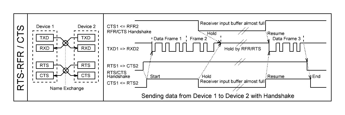
The RTS/CTS handshake protocol was invented to mutually flag send and receive readiness in PTP mode. It uses two additional lines, RTS (Request to Send) and CTS (Clear to Send). In each device RTS is an output, CTS an input. Both lines are cross-connected like TxD and RxD with the known cross-naming issue.
Older devices like modems with PTP and bidirectional lines used RTS and CTS to mutually request access to the common bus. If one device wants to send it activates its RTS line and waits until CTS is set to indicate that the opposite device can listen.
This protocol is nowadays replaced by the more simple RFR/CTS one. The protocol was redefined to stop the sender when the receiver buffer is about to overflow. The RTS signal was renamed to RFR or RTR (Ready for/to Receive), but RTS is still the known name. How is the protocol flow?
The sending device permanently monitors its CTS signal (RFR of the opposite device). It is assumed to be permanently active, but if the receiver’s input buffer (FIFO) is about to overflow this signal is deactivated.
As a reaction on deactivated RTS or RFR the sender has to stop sending as fast as possible; of course not aborting the currently transmitted character, but directly after it. Every additional character can lead to overflow in the receiver, depending on its input buffer size.
This controlling should not be done by software because of the additional delays. It should be directly implemented in the sending module, the UART. It is not possible for synchronous transmission since no data gap is allowed.
The difference between both protocols is that RTS/CTS is an bidirectional mutual handshake while RFR/CTS is an unidirectional handshake, the CTS line is not used while sending. In this case only one signal is used for each direction, so an independent parallel sending and receiving is possible. The protocol can be used for PTP connections only, so it is often found in RS232 connections and rarely in RS485 connections.
Be careful about the polarity of the signal, the Uarts send and receive the control signals inverted, the names are RTS#, RFR#, CTS#.
The RTS signal is also used for special switching purposes if not used as a protocol line. One application is to switch RS485 senders onand off in RS232 to RS485 converters. In this case the RTS signal has to be connected to an appropriate enable signal from the UART (if offered by the hardware) or must be controlled by software. This requests software which enables and disables RTS as an infolding frame to the sent character frames.
DTR to DSR Handshake
Another handshake combination is DTR vs. DSR. It is rarely used in RS232 connections. The name exchange issue also applies for these two lines.
With a high level on DTR (Data Terminal Ready) the master signals its basic working readiness to the slave device which answers in the same way with setting its DSR line (Data Set Ready). So this handshake is used to indicate the general device availability status while RTS/CTS exchange the lower priority state of the data transmission units.
Today DTR/DSR is no longer used except for special applications. If a handshake is necessary the RTS/RFR and CTS handshake is sufficient because if RTS is set on both sides to show the transmission readiness it automatically implies that the devices themselves are correctly working.
Pin assignment
The first design of the RS232 standard connector used a 25 pin D-Sub connector (Subminiature, looks like a D). In addition to the already mentioned 8 handshake lines plus ground a lot of signals were defined for auxiliary transmission channels together with control signals to set the transmission environment like speed and quality. We do no longer care about these signals.
To save money and space the 25pin connector was shrinked to 9 pin with focus on the most important signals to connect to modems. We now have the 9 pin D-Sub connector in male (plug) and female (socket) versions, with male on the PC or Master (DTE) side, and socket on the device (DCE) side.
Gender changers and tools
Most time connecting RS232 units is easy when we have defined masters and slaves, the plug connector fits into the socket connector. But the world is not always that easy.
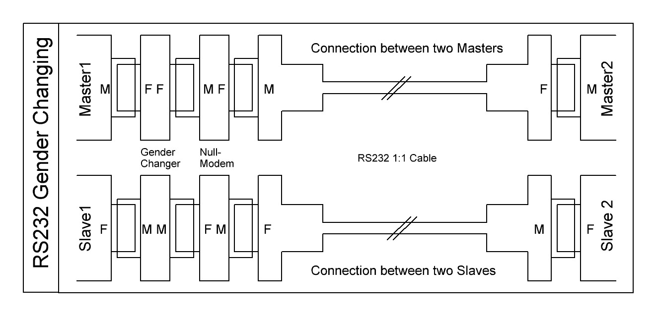
Sometimes masters can also act as slaves and vice versa, sometimes two complementary serial channels are installed and of course masters can exchange data with their kind via RS232. And we already had devices in hand with a plug pinning in a socket connector. The result is that sometimes connections has to be made between two plugs or two sockets or/and wire crossing.
And furthermore different cable types exist. Beside the standard cable with male and female connector and direct 1:1 connection some cables exist with males or females on both sides. And some have crossed wires inside (null modem cable, see below). And do not forget cables with the old 25 pin connector.
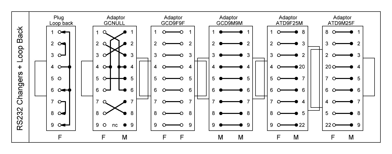
For all these conditions we need gender changers to adapt the cables and connectors to our needs. Seven adaptor types and tools are mainly used.
- Two to turn male into female and vice versa. They contain 1:1 connections between two male or two female connectors.
- Two to connect between 25 and 9 pin
- One to exchange the flow direction, turning master into device and back, called null modem. It does the crossing of TXD-RXD, DTR-DSR, RTS-CTS. DCD is mostly connected to DTR, RI is unconnected or connected to DTR.
- One as a tool to help designers to verify their program or to test a serial port by feeding back the send data and controls to the inputs of the same port, the loop back connector. As for the null modem DCD and RI is connected to DTR.
- And we often use a cheap LED-tester to verify the data flow and status of the controls in an easy manner without complicated test equipment. The RS232 lines are connected to two LEDs each through 4k7 resistors.
Isolation
If the interface has to be isolated for security or ground-breaking reasons two main isolator types are used. Direct isolation between the RS232 lines or isolating in connection with USB to RS232 conversion. For both types a lot of competing products can be found on the market.
The isolation itself is not complicated because of the low bit rates but there are some traps in the practical use to be aware of.
The most important thing you have to care for is that you never use an isolator which draws its supply current from the RS232 line itself. There are a lot of cheap RS232 isolators available without additional power supply and all the manufacturers promise that this works well, but it does not, at least not always reliably.
What is the reason that drawing current from the RS232 input lines to operate the isolator chips and RS232 output drivers does not sufficiently work?
The question contains the answer. If you draw off current from the RS232 inputs for the isolation cicuits this energy is no longer available for the RS232 outputs. In addition the energy buffer burdens the inputs capacitively which increases the rise and fall time of the signal edges and thereby decreases the transmission rate.
From our experience we recommend: Hands off isolators without auxiliary power supply. Isolating USB to RS232 converters draw the energy from the USB line, so this normally does not cause problems.
Conversion to unipolar levels
Independend of the bipolar standard most receivers simply decode the bit level at a voltage of about +1.5V with some hysteresis, they do not care about the invalid state. Knowing this it is easy to use simple and cheap CMOS inverters with 3.3V or 5V working voltage to serve the RS232 lines.
An inverter output can be directly connected to a RS232 input. The reverse direction only needs a current limiting serial resistor of 5 to 10kΩ from the RS232 output to the CMOS input. The clamping diodes to the operating voltage and ground are already included in most inverter inputs (consult their datasheets).
Especially the decoding of the diverse slow handshake lines can be done in this way.
That trick works pretty well when you neclect the intended reliability of the RS232 standard, therefore we recommend to use it for internally used RS232 connections only.
Conversion to other standards
USB to RS232 converters establish serial communication (COM) ports. Pay attention to sufficient bit rates, a complete hand shake set and reliable software drivers for the PC operating system.
RS232 to RS422 converters directly change the levels for PTP/FDX connections. The RS422 driver is always active. The conversion is easy.
RS232 to RS485 converters are more complicated. The RS485 outputs have to be enabled when RS232 data is on the line. Normally these converters enable the RS485 drivers with the edge of the start bit and disable the drivers after a time out when no data is on the line. This time out has to be adjusted according to the used bit rate and is very error-prone.
A better way is to disable the drivers after the RS232 line is inactive for two bytes. That works for all bit rates but these converters are a bit more expensive.
To get a reliable connection regard for all converters:
Don’t use them without auxiliary power supply as the RS232 lines do not have enough power to supply RS485 or other output drivers.
Trouble shooting
The following is a summary of the above chapters. If the RS232 connection does not work check the following, even if it seams trivial:
- Are the cables correctly installed and unbroken, especially in respect of the diverse wiring schemes mentioned above? Use a Led Tester to check the correct data and handshake lines at both sides of the connection. Sometimes a simple cable exchange is a marvel.
- Are the interface settings really the same on both sides?
- Does the cable length fit to all used transmission rates, even if the rate is switched by software. A connection is quickly extended with a another cable but suddenly the transmission gets unreliable.
- Do you use any converters or isolators? Make sure that they are not sourced from RS232 but externally. Regard the hints in the above isolator/converter chapters.
- If errors occur despite a correct cabling then the data stream might be faulty, caused by erranous software or timing. To examine these errors an independend hardware based RS232 analyzer with high timing resolution is the first choice.